




Common Battery and Inverter Communication Problems and Solutions
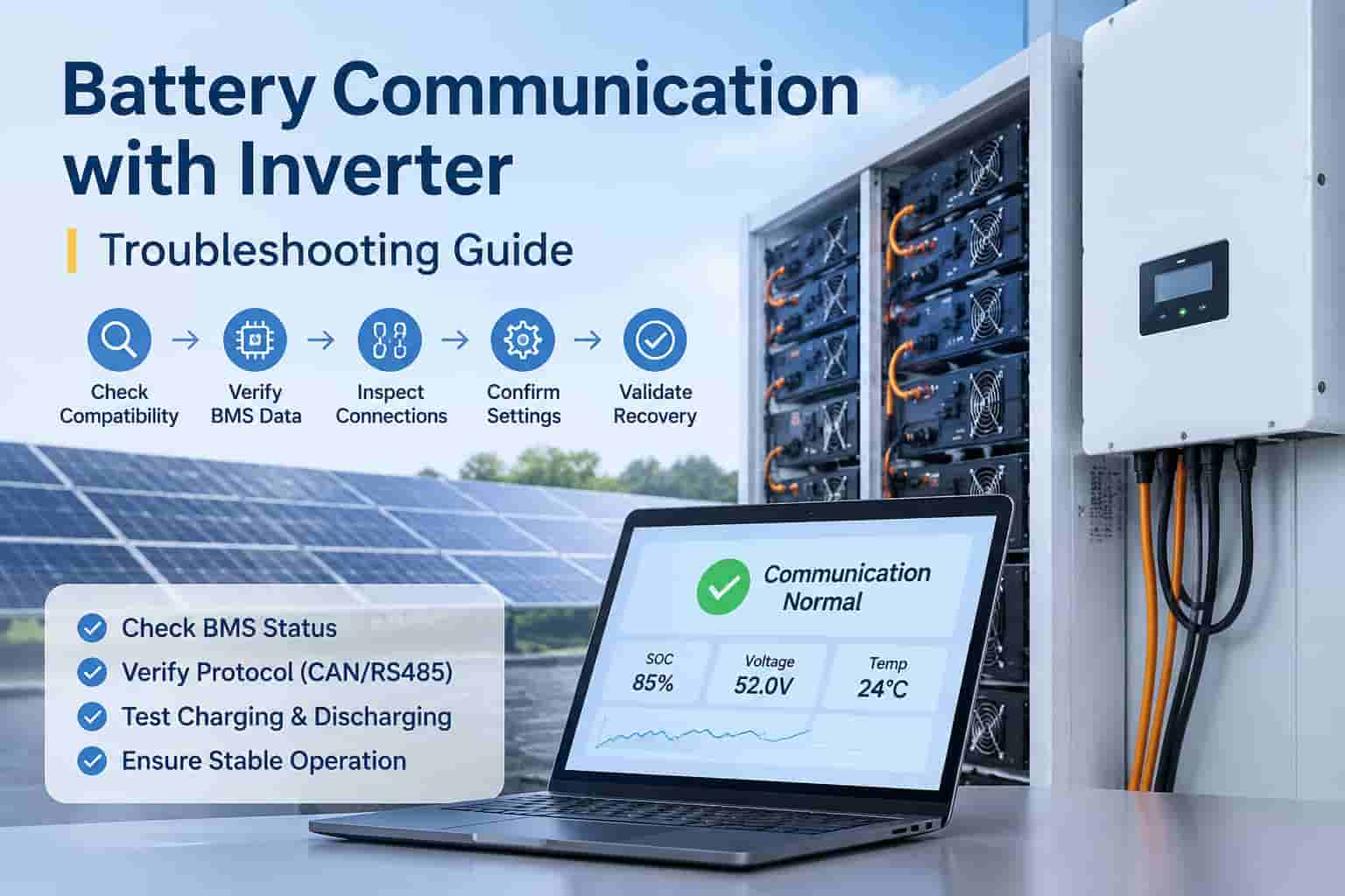
Troubleshooting battery communication issues with an inverter requires checking hardware connections, communication protocols, and system compatibility. Start by confirming that the battery and inverter are officially compatible. Next, inspect the Battery Management System (BMS) status, communication interfaces, cable specifications, protocol settings, and firmware versions to identify potential communication errors.
After making the necessary adjustments, verify that communication has been successfully restored by monitoring real-time battery data and conducting a controlled system operation test. Keep in mind that displaying battery voltage or State of Charge (SOC) alone does not necessarily indicate successful BMS communication.
For commercial solar energy storage systems, a systematic battery-inverter communication diagnosis is essential to identify whether the issue originates from communication interfaces, battery protection mechanisms, inverter control settings, or internal faults within the battery rack. Proper troubleshooting helps ensure reliable data exchange, stable system operation, and effective coordination between the battery and inverter.
What Data Is Shared Between a Battery and an Inverter?
The Battery Management System (BMS) continuously monitors battery operating conditions and transmits essential performance data and operating limits to the inverter. Depending on the battery and inverter models, the exchanged information may include State of Charge (SOC), battery voltage, temperature, maximum allowable charging and discharging current, and system alarm signals. The inverter processes this data together with its configured parameters and site-level control requirements to manage battery operation safely and efficiently.
Battery-inverter communication commonly relies on CAN (Controller Area Network) or RS485 communication interfaces. However, using the same communication interface does not automatically guarantee compatibility. Both devices must support matching communication protocols, compatible data formats, and appropriate firmware versions to ensure reliable BMS data exchange.
It is also important to distinguish between connector types and communication standards. For example, an RJ45 connector does not necessarily indicate an Ethernet connection. Similarly, using a standard network cable does not guarantee correct communication, as the cable pinout and wiring configuration must meet the battery and inverter manufacturer's specifications.
Collect System Information Before Troubleshooting
Before modifying any inverter settings or battery configurations, gather detailed system information to establish a clear starting point for troubleshooting. Record the battery and inverter model numbers, serial numbers, firmware versions, exact error messages, and the time when the communication issue first occurred. Also, identify whether the problem appeared after initial system commissioning, battery capacity expansion, communication cable replacement, or a firmware update.
It is equally important to check the local display screens of both the inverter and battery at the same time. Local equipment readings generally provide more immediate operating information, while cloud-based monitoring platforms may experience data synchronization delays. Therefore, outdated values on an online monitoring dashboard should be investigated separately from actual battery-inverter communication faults.
The following table outlines common battery communication symptoms and the recommended areas to inspect first:
Observed Symptom | Recommended Troubleshooting Area |
|---|---|
Battery voltage is displayed, but real-time BMS data is unavailable | Check battery-inverter compatibility, communication ports, cable connections, and protocol settings. |
BMS data is updating normally, but the permitted charging current is zero | Inspect battery temperature, SOC, active alarms, and BMS protection limits. |
Battery communication frequently disconnects during operation | Examine connectors, cable routing, shielding, auxiliary power supply, and system event logs. |
Communication errors occur after adding battery modules or racks | Verify supported battery configurations, module quantities, device addressing, and communication termination settings. |
Local battery and inverter data are up to date, but cloud monitoring information is delayed | Check the monitoring gateway, network connection, and data synchronization status. |
Follow a Step-by-Step Battery Communication Diagnosis
1. Verify Battery and Inverter Compatibility
Check the battery voltage, supported inverter model, regional version, and firmware requirements. Similar model numbers do not guarantee compatibility. For multi-rack systems, ensure the battery controller and rack configuration are approved for the complete installation.
2. Check BMS Status and Battery Alarms
Confirm that the Battery Management System (BMS) is powered on and has completed its startup process. Review alarms related to internal communication, insulation, temperature, pre-charge, and contactors. A battery may communicate normally while restricting charging or discharging due to active protection limits.
If you detect physical damage, excessive heat, smoke, or electrical protection alarms, stop troubleshooting and follow the manufacturer's emergency procedures. Only qualified personnel should inspect or reconnect cables after proper shutdown and electrical isolation.
3. Inspect Communication Ports and Cables
Check the connection between the inverter's designated battery communication port and the battery or master controller. Avoid confusing communication ports with inter-battery links, service interfaces, or monitoring ports.
Verify the cable model and pinout against both manufacturers' manuals. Inspect connectors for damage and use an approved replacement cable if necessary. Never assume a standard Ethernet cable has the correct wiring.
4. Verify Communication Protocol and System Configuration
Confirm the selected battery type and communication protocol. Check baud rate, device addressing, master settings, battery module count, and termination requirements according to the equipment documentation.
Avoid copying DIP switch settings or resistor configurations from other battery models. Change one parameter at a time and record the original settings to simplify fault identification and recovery.
5. Check Firmware Compatibility and Restart Procedures
If communication problems occur after a firmware update, provide the battery and inverter software versions to technical support. Only install manufacturer-approved firmware combinations.
Follow the specified shutdown, restart, and waiting procedures. Avoid repeated power cycling without identifying the underlying communication fault.
How to Verify Successful Battery-Inverter Communication
To confirm that battery-inverter communication has been restored, check whether real-time BMS data updates correctly and matches the readings on the battery display. Verify key parameters, including State of Charge (SOC), battery temperature, permitted charging and discharging current, active alarms, and the number of detected battery modules or racks.
With proper installer authorization, conduct a controlled charging and discharging test within the manufacturer's specified operating limits. Ensure that the inverter correctly follows BMS operating restrictions and maintains stable communication throughout the test.
Finally, document the test results, system configuration, firmware versions, and any replaced components. Proper records help verify communication recovery and simplify future maintenance and fault diagnosis.
FAQ About Battery-Inverter Communication
Does an SOC Reading Confirm Successful Battery Communication?
No. SOC values may be cached, estimated, or delayed. Check real-time BMS data, charging and discharging limits, and active alarms through the equipment's diagnostic interface.
Are CAN and RS485 Communication Protocols Interchangeable?
No. CAN and RS485 are different communication interfaces. The battery and inverter must support the same interface, compatible application protocols, and correct cable configurations.
Can I Bypass BMS Communication to Restore Inverter Operation?
No. Never disable BMS protection or select an unsupported battery mode to bypass communication faults. Alternative operating modes require explicit manufacturer approval for the specific battery-inverter combination.
Why Does a Battery Communicate but Refuse to Charge?
The BMS may restrict charging due to SOC levels, cell conditions, temperature, or active protection alarms. Inverter charging schedules and site control settings may also prevent charging. Check BMS limits and fault history before replacing communication cables or components.